 flash adapter with shrink tube
Flashbars are not produced anymore.
If you have a SX-70 camera it is highly recommended to buy an
electronic flash for it.
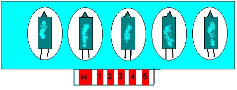
The Flashbar contains on each side five glass bulbs that are
filled with magnesium wool in an oxygen-atmosphere.
The magnesium is ignited by an electric pulse.
The glass bulbs are plastic-coated to prevent them from
exploding.
The outer plastic wall is another safety-shield and corrects the
light-color.
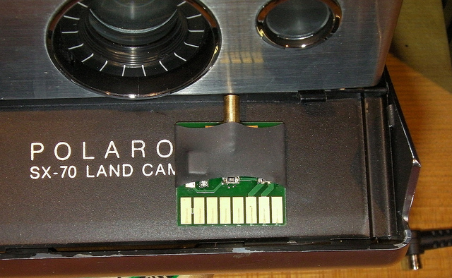
The Flashbar is contacted from the front (active-)side.
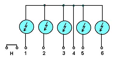
The camera knows which bulb has been fired by measuring the
resistance across the bulb.
A good bulb has a resistance of a couple of ohms whereas a dead
one has almost infinite resistance.
There are several reasons to use an electronic flash instead
of the flashbars:
There are electronic flashes (Polatronic, ITT Magicflash etc.)
that were designed for the SX-70 which are clamped to the camera
and plugged in the flashbar connector.
Note that Polatronic flashes designed for Pronto and 6XX cameras
do not fit the SX-70.
A good place to look for one is the
rec.photo.marketplace-newsgroup.
If you already have an ordinary electronic flash that you
want to use with your SX-70, you need an interface.Note that the flash needs to have similar power as the
flashbars, which is slightly more than the average photo flash
provides.
Flashbars have a fixed light output that reaches to a distance of
about 3 meters (10 feet).
The SX-70 exposure control is based on the focused distance.
The camera's maximal aperture (f-stop) is 8.
Your flash should have a guide-number of 75 (9,5 feet * 8)
or a metric Leitzahl of ca. 25 (2.9 meters * 8) at 125 ASA.
A flashbar-camera generates an electric pulse of ca. 4V , 1.5A to trigger the flashbulb.
An electronic flash has a voltage of ca. 3-12 V between the
trigger-contacts (older flashes have up to 300 V !) that are shorted to trigger the flash.

flash adapter with shrink tube
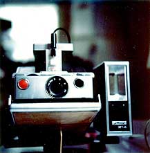 Here is a picture of the
adapter with my SX-70 and my Metz flash:
Here is a picture of the
adapter with my SX-70 and my Metz flash:
For a DIY project I recommend cutting a dead flashbar open and using its contact strip and its plastic enclosure.
All components are soldered to the front side and it is recommended to cover the circuit with epoxy, especially the output side of the coupler for safety (flash-contacts).
If you would rather buy a complete, tested SX-70 flash-interface look at my flash adapter website
Click here for information about how to modify your SX-70 so it always keeps the aperture open in flash mode (to use the interface with studio flash setups or computer-flashes).