636 Flash for SX-70 Sonar

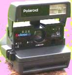
Stephan Wagner has converted the flash from a Polaroid 636 into an external flash for his SX-70 Sonar
Translation by George Holderied. The german original text is here.
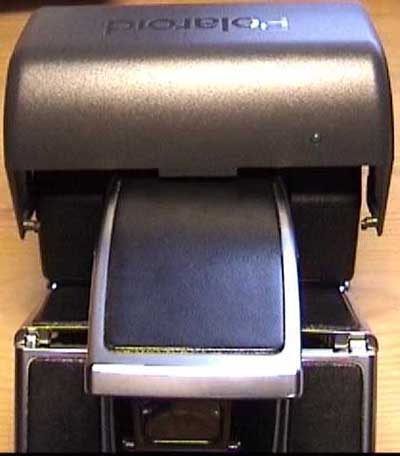
The flash has a flashbar socket and can be removed from the camera.
No changes need to be made to the camera.
Flash features:
- The flash is supplied with power from the film pack battery inside the camera.
Because of this it can only be used with Sonar-AF cameras which have four extra contacts at the rear of the flashbar socket.
- Recycle time is ca. 1.5 seconds.
- Camera shutter is blocked until flash is ready.
- Flash recycles after image is ejected and shutter button is released.
- After pressing the shutter button flash recycling is inhibited until shutter is released and focus is back to park position.
- When focusing manually, the shutter must be kept pressed until the picture is ejected.
Here I cannot inhibit recycling automatically because the contacts give me no information whether the eject motor is still spinning.
(The battery does not have enough power to eject / focus and recycle the flash at the same time.)
- The flash can be switched off (to conserve battery power and while it is plugged in or removed).
- The most difficult thing was to find a suitable connector that fits the flashbar slot, as it also uses the rear contacts.
I've used a print from a defective Polatronic 1 flash and some Vero-Board for the rear contacts.
Contact strips from used flashbars could be modified as well.
List of components:
- 1 Polaroid 636 camera or similar with working flash.
- 1 resistor 10 Ohm 0,5 W
- 1 resistor 4,7 k Ohm 0,25 W
- 1 resistor 10 k Ohm 0,25 W
- 1 resistor 10 k Ohm 0,5 W (only used to discharge the flash capacitor)
- 1 electrolytic capacitor 100µF 350V
- 1 electrolytic capacitor 33µF or 47µF 350V
- 1 capacitor 470pF
- 2 diodes 1N 4148
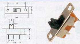
- 1 Mini-switch
- ca.1m stranded wire for connection. Using different colors helps to keep track of connections.
- I've bought all components at www.Reichelt.de for about 20 DM (10 US$)plus shipping
- I've snapped the Polaroid 636 up at ebay for 20 DM
- WARNING Inside electronic flashes there is dangerous high voltage !
Conversion:
- First try the camera with an empty 600 film pack. Only the flash needs to work. The rest doesn't matter
After testing the flash you can start to dismantle the camera:
- Remove the film pack.
- Open the flash 45 degrees. Now you can unhook the hinges.
- Cut the ribbon cable.
- The flash unit can be opened from the bottom side. There are two holes next to the hinges. Push the tabs in and lift the lid carefully.
- Discharge the HV capacitor (The big one)through the 10k Ohm resistor 0,5W for at least 10 sec. Hold the resistor with an insulated tool ! Danger High Voltage! The resistor becomes hot!
- Remove the print circuit board, (pull flash upward).
- Unsolder the HV capacitor, TH1, Q9 and the ribbon cable connector. Q9 is needed later the rest can be discarded.
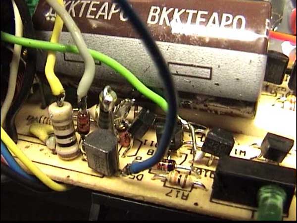
- Cut the corner for the switch and cut the PCB trace (see PCB picture below)
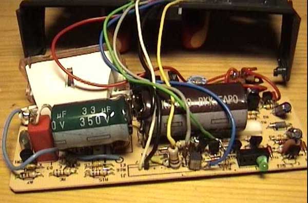
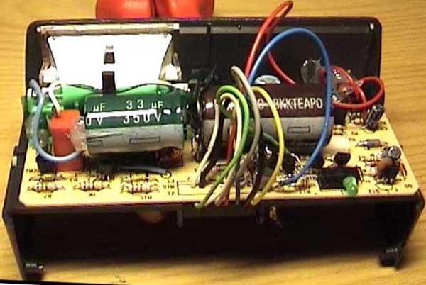
- Mount the 100µF capacitor where the flash capacitor was (Polarity!). Keep the wires at the PCB bottom as short as possible.
Mount the33µF capacitor in parallel (see pictures below). This results in a total 133µF and fits well into the flash enclosure.
One can also use a 47µF cap instead of the 33µF. I found this results in slightly overexposed images, and space gets tight inside the enclosure.
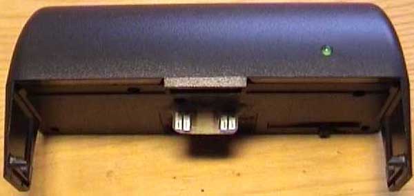
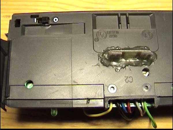
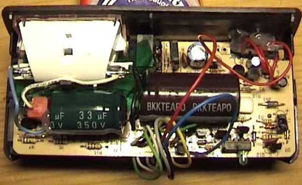
- Modifications of the flash bottom. File a hole for the switch and cut a slit for the flash socket connector (see pictures). The flash connector is glued in place with epoxy so that it protrudes about 1mm on the inside.
- Now solder: (contact # are numbers at the ribbon connector)
- From # 3 to the emitter of Q10 the 10k Ohm 0,25 W resistor . Emitter Q10 is "(3)"
- From # 3 and R1 at the side over #3 the 270pF-capacitor .
- Unsolder the collector of Q6 and bend it upward. Stick the anode of a 1N4148 diode in the hole where the collector was.
solder the anode to the print and the cathode to the collector of Q6.
Solder the 4,7 KOhm resistor to the solder joint between anode and collector.
- Solder the second 1N4148 diode in #1 cathode towards the PCB.
Leave enough space in between PCB and diode, that you can solder the collector of the removed transistor Q9 there.
the anode of that diode is "(2')"
- The base of Q9 goes to the other end of the 4,7k Ohm resistor.
- The emitter is "(8')" (I've used a BC 556 instead of Q9, because I didn't know yet if Q9 is used in its original place.)
(In the pictures below there is a BC556 in the place of Q9). As Q9 (2N3906) and BC556 c and e are the other way, the BC556 must be mounted upside down. (see circuit diagram).
- After connecting the cables to the socket connector it is crucial to add 3-4 layers of insulating tape over the solder joints
so that the contacts cannot touch the PCB.
Right in the center of the PCB where I placed the socket connector are the 330 Volts which, if they made contact the socket that would destroy the camera.
After insulating the contacts the PCB is put back into the enclosure..
The switch and the 33µF capacitor are fixed with hot glue. Now put the cover back and the flash is finished.
- The resistor 10 Ohm goes between #2 and "(6)"
- connect #6+#5 to "(8+7)"
- connect #7 to "(1')"
- connect the new switch at the two cut traces where the original switch used to be:
the outer trace goes to the center of the switch.
the other trace goes to one outer contact of the switch.
the other side of the switch goes to (7')"
Now connect the contacts to the flash socket connector.
(Note that I am using the numbers from the Polatronic 1 print, which is the other way from the numbers George uses with his
flash adapters)
The meaning of the numbers in brackets:
(1)- flashbulb 5 NC
(2)- flashbulb 4 NC
(3)- Power supply from Flash IC (+6V)
(4)- flashbulb 3 NC
(5)- flashbulb 2 NC
(6)- flashbulb 1 flash trigger
(7)- connect to GND for flash mode (camera)
(8)- GND
The contacts with ( ' ) are opposite to the respective contacts
(1')- + voltage when focusing(shutter button slightly depressed)
(2')- + voltage when taking (shutter button fully depressed)
(7')- + voltage when camera unfolded
(8')- + voltage when camera focus not in park position
Contacts of the ribbon cable:
#1- + voltage inhibits recycling (input)
#2- + voltage when flash is ready (output)
#3- triggers flash when connected to GND (input)
#4- stops the flash when connected to GND (input)
The 636 has a computer flash function. When there is enough light reflected from the object, the flash
is stopped by discharging the HV capacitor through TH1.
As the SX-70 couples the aperture to distance in flash mode there is no need for this function here.
#5+#6- GND
#7- + supply voltage of the flash circuit
Why have you changed the HV capacitor??
I have converted my SX-70 to 600 film by changing the inttegrator capacitor in the shutter module from
1100pF for 270pF. This has no influence to taking flash pictures other than I use 600 film normally - not SX-70 film.
If you only use 600 film for flash pictures no changes to the camera are neccessary, but for daylight
pictures a 2 stop gray filter must go in front of the lens as 600 film is 4x faster than SX-70 film.
The 636 camera's computer flash electronics are in the camera body, not in the flash unit.
The SX-70 needs a constant power flash (such as flashbulbs in the flashbars) and sets its aperture accordingly.
The original flash capacitor has a capacitance of 406µF.
My first test picture with 600 film was grossly overexposed so I reduced the capacitor's size until I got correct
exposure with 600 film.
One could also try to reduce the 330V high voltage,
but there is no easy adjustment, one would have to change the Z-Diode.
It is not sure if the flash lamp would still ignite at the 110V necessary.
The original capacitor is almost enough to expose a SX-70 film,
if the exposure wheel is set towards 'brighten'.
I don't know if the battery can supply enough energy. (But it does in the 636)
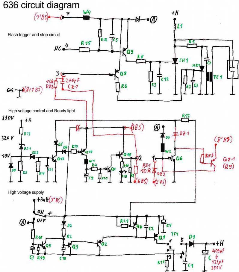
Circuit diagram
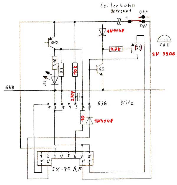
The components in red were added. I have only drawn the most important
components of the flash circuit.
Sketch of the complete 636 flash circuit.
Technical description:
1. Original function of the 636 camera 636:
The flash is charged when it is flipped up. This is initiated by the switch on the piece of PCB that we cut away.
When the flash is ready the LED lights up , and #2 goes to +6V. The camera is ready.
When pushing the shutter button slightly, #7, and the flash are supplied with power.
When the shutter is pressed fully the shutter opens and, the flash is triggered by #3.
If there is enough light collected from the electric eye, the flash is stopped via #4.
The shutter closes. #1 inhibits recycling of the flash until the picture is fully ejected.
2. Function SX-70 Sonar with the 636 flash:
The flash charges up when it is switched on. When it is charged, Q10 switches the 10 Ohm resistor from (3) to (6). That
simulates the presence of a flash bulb and enables the shutter. I have ve found the value 10 Ohms by experimentation. I wanted to make it as big
as possible in order to save Q10 - I could not find technical data for this transistor type.
George uses 3.9Ohms in his flash adapters. If there are trigger problems, one could try lower values..
When pushing the shutter button slightly, (1') powers #7 . Without the 10k Ohm this would trigger the flash through the 270pF capacitor.
The flash unit has now power from the battery.
When the shutter is pressed fully, at the moment of maximum aperture (6) is shortly pulled to GND. Current flows through 10 Ohm resistor and Q10.
The voltage drop over Q10 reaches the very sensitive flash trigger #3 through the 270pF capacitor.
The flash is triggered and remains on until the flash capacitor is empty.
.
#4 has no function.
Q6, Q9 and the 4,7k Ohm resistor keep #1 (recycle inhibit) to +5V until the AF is back to park position or the shutter button is not fully depressed anymore.
The two 1N4148 diodes are for decoupling.
Q6, Q10 and some other transistors in the flash have integrated base resistors.
Do I have to emphasize that I cannot be held responsible for any damages?
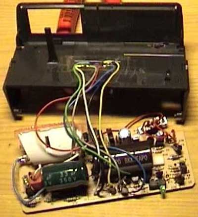
Pictures
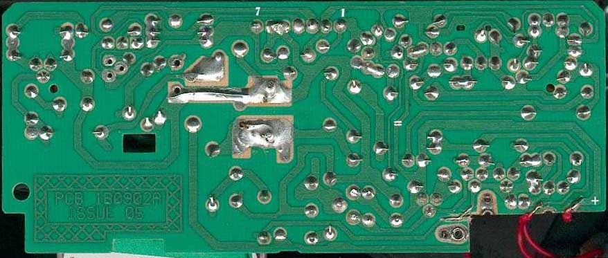
Underside of the PCB Cut the track at the "=" .
The"+" on the picture "+" corresponds to the "+" in the circuit diagram.

A picture of Stephan's daughter Sara, taken with the 636 flash.