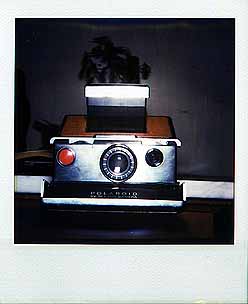
How to disassemble a SX-70 Camera
This article is work in progress.
I am going to describe the sections in more detail in the future.
Don't blame me if you damage your camera following my instructions.
The pictures were done on heavily outdated (+2years) SX-70 film, so their
quality is not as you could expect it from a SX-70 with new film.
Thanks to Chris Czopek for providing some cameras for research.
Tools
Get a service-manual.
There are PDFs of the SX-70 service manual and the Sonar supplement for it floating around on the internet.
Some people sell them but if you look around you will find them for free.
You will need a Torx T4 or 1mm square (Robertson) screwdriver.
Some cameras also require Torx T5 or square section screw drivers, but I
didn't encounter any of these yet.
Don't even think of opening the screws with a blade or a hex screwdriver,
you will ruin the screws and eventually the tool.
Good tool dealers will sell you a T4.
Others will tell you that the smallest Torx size that exists is T5 (!).
A paper clip bent to L-shape is useful to push the pins out.
Pliers to hold the Paper clip.
Most of the screws and pins in different places are slightly different
in shape /size.
It is recommended to note the position of each screw so you can put them
back in the right places. I stuck them with adhesive tape on a sheet of
paper and wrote the place of origin next to each.
The SX-70 and its sections:

A: Main Body
B: Roller assembly
C: Shutter assembly
D: View finder
E: Bellows
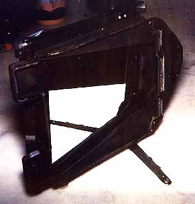
A: The Main Body
Carefully peel the leather off the big bottom piece.
If it is real leather, there is a sheet of aluminium foil under it that you
should peel of together with the leather.
The glue is strong, be careful not to stretch/wrinkle/dent the aluminium foil.
If the camera is covered with plastic "Porvair"
then it is likely that you will tear the cover.
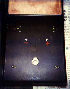
Under the cover there are four screws that hold the bottom shell in place.
Two holes give you access to the battery contacts.
Remove the screws and take the bottom shell off.
B: The Roller Assembly
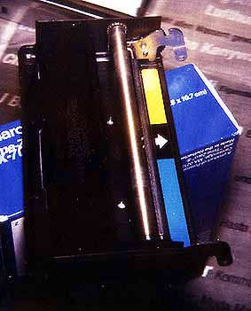
The roller assembly is the part that folds down when you load a film pack.
It contains the two rollers that develop the film, the sheet metal spring
at the bottom where the photos are ejected and a light shield (The flap
with the name of the camera on it).
Dirty rollers will lead to spots repetitive patterns on the pictures. A
bent output spring will let some light in that ruins the pictures.
Never peel off the leather from the roller Assembly. It is glued to the
output spring and the spring will bend before the leather comes loose.
To remove the roller assembly simply push the hinges inward to release
them from their bolts and unhook the whole assembly.
C: The Shutter housing (regular as well as
Sonar models)
This section was written by Marty Kuhn
- OK. From what limited experience I have here, I've found that this
task can be either very easy or frustratingly difficult depending on the
manner in which your particular camera was originally assembled and how
well-stocked your tool box is.
- If you're lucky, all you'll have to do is gently pry up on the lower
back corners of the shutter housing cover. Look at the side of the shutter
housing where the two-pin jack for the remote shutter button is located.
In the lower corner, there's a notch in the cover for the wires that connect
to the film battery and the ejection motor. With a fingernail or a small
screwdriver, pry up on that corner, and work it towards the front of the
camera. Do the same thing with the equivalent corner on the other side.
If you look carefully at the underside edges of the shutter housing, you
can see how it locks onto the frame. (george: it is a lot easier to do
this when the lens is fully retracted in the 'infinite' position.)
NOTE: Although the shutter housing front cover *does* look like solid metal
at first, it's really chrome-painted *plastic*, so be careful! If the cover
doesn't seem to want to go anywhere after some gently coaxing, then you're
probably gonna be in for it, so check out the next step: :-)
- If you're *unlucky*, there are also two screws which hold the front
cover to the shutter housing. Don't bother *looking* for those screws right
now, because you can't see them. :-( They're not accessible until *after*
you remove the entire shutter assembly from the camera body. "But,"
you say, "I can't remove the $%&*@# cover! So what do I do now?"
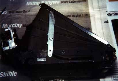
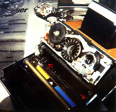
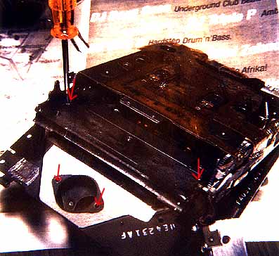
Well, look behind the shutter housing, (the side where the bellows attaches
to it) and you'll see 4 little black screws-- 2 on each side.
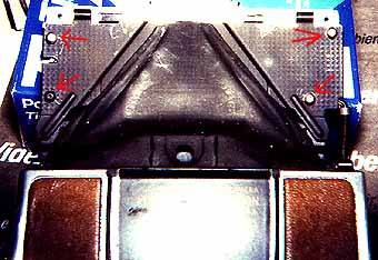
(viewfinder removed on this picture fro better visibility)
Now, this *looks* simple, but you may find it difficult to find
a tool which will fit those screws (they will either be very small Torx
heads or very small square heads depending on the age of the camera), so
if you're like me, you'll probably just try to go with what you've got...
So, if you're in luck, maybe you've got a small standard jewler's screwdriver
which will fit the heads reasonably well-- and *hopefully*, the screws
won't be *too* tight, and you won't strip the heads in the process...
[george: Use the proper Torx T4- tool, I broke two jewellers srewdrivers
:-( ]
Obviously, you should be careful not to damage the bellows while you do
this. Once you've got the 4 screws out, the whole shutter assembly will
fall off the mounting plate-- though it may stick a bit because the foam
light-sealant between it and the plate. A good thing to do is just let
it fall into the front recess (where the shutter ends up when the camera
is in its folding position). *Now*, you'll be able to see two Phillips
head screws at the top of the shutter assembly which hold the front cover
on.
Remove those two screws, and *then* you can remove the front cover! Finally!
*Now*, you get to re-mount the shutter assembly to the plate, and re-fasten
those 4 pesky little screws, because working on the shutter assembly is
a lot easier when it's fastened in place, and there's nothing you can adjust
or see from the back anyway. Having fun now? :-)
- In either case, at this point you should now have an SX-70 with the
front cover removed. Those of you in the "lucky" condition can
see where those hidden screws were *supposed* to go by noting the two holes
in the shutter assembly which correspond with the two screw threaded receptables
in the cover. My guess is that the older models have the screws, but then
Polaroid Corp decided that the friction fit was all that was needed. Speaking
of which, if you were in the "unlucky" condition, you can probably
just omit those two extra screws if you want when you re-assemble the camera--
they're really not necessary, they don't affect the outside appearance
of the camera, and you might not want to go through that same routine if
you ever have to disassemble this thing again.
- Now that you have it open, you'll note that the shutter button with
its little plastic mount stays attached to the front cover, and makes electrical
contact via a pair of little leaf "fingers." Anything that might
be jammed in the shutter or focusing mechanism should be fairly self-explanatory.
You'll also note that there isn't much you can do as far as *adjusting*
anything goes-- there aren't any electrical adjustments that I can find,
and in fact, the CdS cell is *part of* one of the IC's surface-mounted
to the back of the circuit board! Well, it *looks* neat, though, doesn't
it? :-) Oh, btw, you *can* operate the camera with the cover off without
fear of anything falling off or flying out on their own accord, unlike
the roll film and pack film cameras-- either use the remote shutter button
accessory, or use a small metal object to short out the switch terminals.
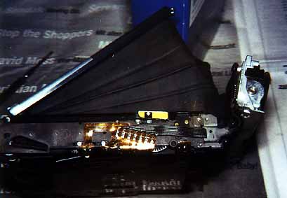
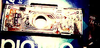
The printed circuit board on the rear of the shutter assembly is the
"brains" of the camera.
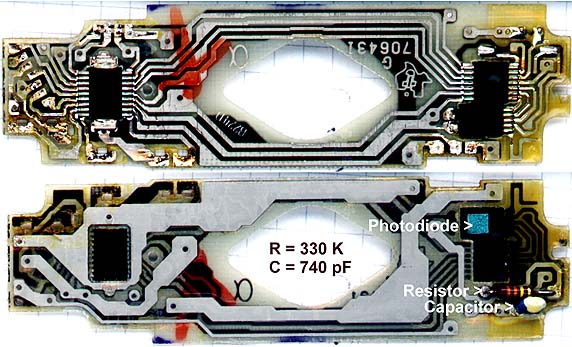
To remove it, carefully unsolder the flex cable and the connections
to the flash- and solenoid units.
My guess is that the resistor and capacitor on the pc board are the key
elements of the integrator that collects the photo current during
exposure.
If this is true the value of the capacitor should be proportional to
1/film speed. Changing the value of C to 150 pF should set the camera
to 600 ASA for 600 film. (I haven't tried this yet).
D: The viewfinder Assembly
The viewfinder and the part of the shell where it is mounted are fastened
with pins that act as hinges to the cameras folding mechanism.
To unmount the Viewfinder unfold the camera and take the shutter cover
off. (see above)
Push the two pins outward with a paper clip bent to L-shape. Note that the
two pins have different lengths, but it is obvious which goes where.
Flip the whole assembly up and
push the two pins out that connect the assembly with the shutter assembly.
E: removing the Bellows
remove the two screws that connect the bellows to the shutter-base two
that attach the bellows to the front plate where the shutter sits (remove
shutter first)
unhook the two latches on the rear on either side that hold the bellows
down 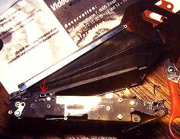
(You may have to unscrew the gear (3 screws)to access the right hand latch,
but I am not sure of that.)

To remove the bellows-assembly, push out two pins in the rear unhook the strut.
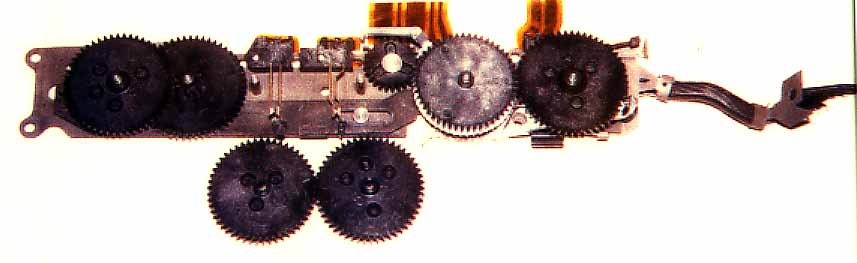
Gear
If the Gear is jammed, you can partially inspect it without disassembling
the camera.
Pry off the plastic gear cover, start at both sides of the release-button
for the film- door.
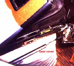
The Gear contains electrical contacts.
Miscellaneous
I still have not found a way to unsolder the camera's flexible printed
circuit board without having it separate in three layers.
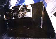
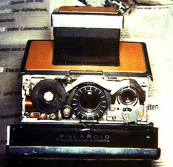
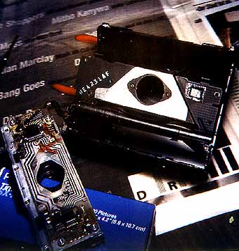
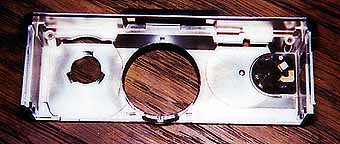
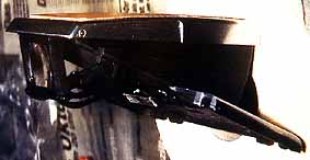
Here is a picture uf a SX-70 with its clothes off:
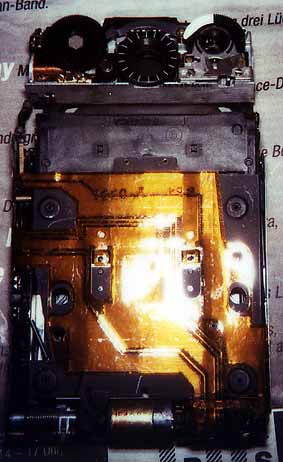
The chassis with the swinging mirror
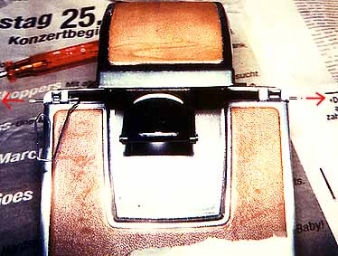
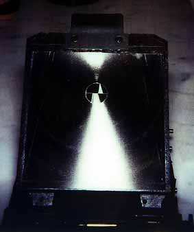
The fresnel-side of the swinging mirror.
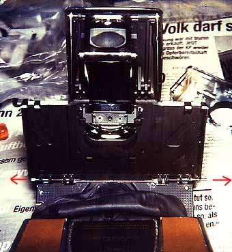
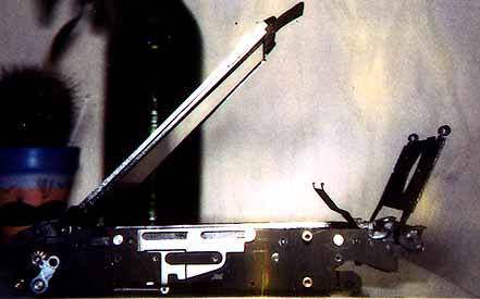
More shots of the naked SX-70: