Abstract:
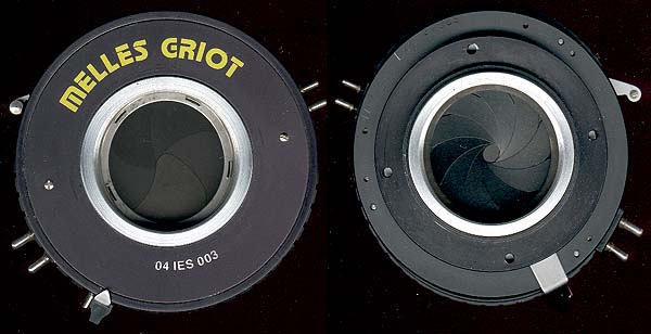
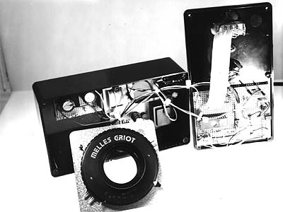
A microprocessor controlled shutter control-box for electrically driven shutters such as the
MELLES GRIOT 04 IES 003 and others, such as the ILEX electric shutters.
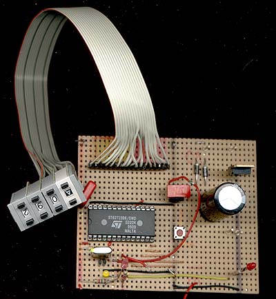
A SGS-Thomson ST6215 is used as the
microcontroller.
Older view camera lenses often come in shutters that have problems from use or age. Usually a clean/lube/adjust service
will restore the shutter but sometimes it is necessary to replace it. New Copal shutters are very expensive and used
shutters in good working condition are rare and also not cheap, especially the large (Nr.3) sizes. Not to speak of the electronic
Copal and Sinar shutters.
An inexpensive alternnative are the Melles Griot electric shutters that appear on ebay now and then and usually go for well under 100$,
mainly because the necessary controller box costs 800$ and has limited capabilities.
This page describes the construction of an inexpensive controller with very high accuracy, many features and comfortable handling.
An inexpensive ST 6215 microprocessor is used (mainly because I have the SGS starter kit). PIC- Atmel- or other microcontrollers
would do the job as well if programmed accordingly.
long time mode: when the first switch is set to 0 all four switches are interpreted as time n seconds
examples: 0005 is 5 s and 0120 is 120 s= 2 min
maximum is 255 s =4 min 15 s
short time mode: when the first switch is set to A the remaining three switches are interpreted as fractions of a second.
The following times are possible: 1/64, 1/32, 1/16, 1/8, 1/4, 1/2, 1 sec. all other settings result in an error message (LED flashes 6x) when the shutter is triggered.
examples: A064 is 1/64th, A008 is 1/8th, A025 or A732 will result in an error.
"B" (Bulb) mode: When the first switch is set to B the shutter acts like any camera in "B"-mode: the shutter is open as long as the trigger is pressed.
"T" (Toggle mode): When the first switch is set to C pressing the shutter button will open the shutter, pressing it again will close it.
Self timer modes When the first switch is set to D,E or F the self timer is active.
the remaining three digits are interpreted like in short time mode. D gives a delay of 10 s, E of 20s and F of 30 s
example: E064 will open the shutser for 1/64th after 20s delay.
Click here for the final circuit (625 MB !)
The outputs of port C can only source 5 mA. I should have used 4 lines of
port C which can source 20 mA which is sufficient for LEDs.
Therefore I had to add three open collector drivers (BC547B)
The processor is very sensitive to power supply spikes.
I use a shutter with a 6V solenoid and first intended to share the
holding voltage with the processor's power supply. This was not a good idea.
I now have two completely separated power supplies for uC and shutter.
with one 5V-supply for the processor and a 8V+22V-supply for the shutter.
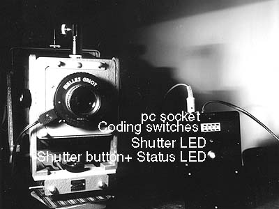
I decided to use coding switches in the controller because they
can serve as input devices, displays and even memories at the same time.
However a rotary input dial with an separate display might be more comfortable
as a user interface
The short time ranges, are now 1/1 1/2 1/4 1/8 1/16 1/30 1/60 1/120 with no intermediate values allowed. Maybe it is better to allow any short time setting. Who wants to write the math routine?
Anyone wants to make a pcb-layout to be be published here ? I'd trade a programmed
processor for a PCB.(I am quite happy with the Veroboard prototype though)
Preferably one including a power supply for 6V and 48V shutters.
Do you have any suggestions ? please email me.